AR2000 BULLETIN PAGE
Archive originally from the AOR-UK website in 2008, edited in 2022 by AOR Ltd. In Japan.
This information is supplied as a convenience to our loyal customers still using discontinued legacy AOR receivers.
Please note that the information is supplied “as is” without any support nor obligation. This model is no-longer accepted for repair and none of the parts are available anymore.
This information is supplied as a convenience to our loyal customers still using discontinued legacy AOR receivers.
Please note that the information is supplied “as is” without any support nor obligation. This model is no-longer accepted for repair and none of the parts are available anymore.
FairMate products
AOR and FairMate products were made on the same assembly line as 'OEM' branded items, their main PCBs and operation are the same but cosmetics are different. The operation of the FairMate HP100/200/2000 and AOR AR1000/2000 are the same.| Keypad |
| DC Socket |
| Microprocessor reset |
| Unlocking Search & scan banks |
| Keypad Beep |
| discriminator (detector) output |
TOP
Replacing the AR2001 membrane keypad
1) Switch the set off and disconnect the power.2) Remove the bottom case half (if you remove the top too then access is a little easier).
3) Unplug the keypad ribbon cable from the connector of the microprocessor front panel PCB.
4) Using the edge of a Stanley knife, carefully peel off the original keypad which is sticky backed.
5) Remove any excess material from the front panel to provide a smooth surface for the new keypad.
6) Remove the sticky-back material from the new keypad. Push the ribbon cable through the lower slot and firmly press (do not crush!) the keypad into place.
7) Gently offer up and press home the ribbon cable into the microprocessor PCB connector.
8) Re-connect power and test then reassemble
Keypad replacement is now complete.
TOP
AR2000 DC SOCKET
The power socket on these units gets a lot of wear and can eventually fail or become intermittent (intermittent supply levels are the main cause of crashed microprocessors in these sets). The socket itself can fail or the solder joints to the board can fracture. Either way, repair is simple, requiring removal of the rear case, 1 earth wire and lifting of the supply board. Replace or resolder the socket but, as a further preventative measure, a wire can be soldered directly to the rear of the socket and taken to the anode of D201 (situated next to the socket).TOP
AR2000 MICROPROCESSOR RESET
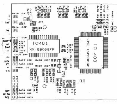
The AR2000 has no external RESET facility. In the case of a 'hang' or corruption, reset the microprocessor in the following manner.There are two methods, one involves connecting a diode between pin 13 and 51 on the microprocessor, this is tricky as track damage and short circuits are easy to create... we recommend the 'wire link' method shown below.

The best method is to add a wire link to the CPU board while the radio is switched off:
Switch the set on and PRESS the KEYS in the following order, the key presses should appear on the LCD as you enter detail... if it will not initiate, you may have to press BANK 1 several times until the number "1" appears:
Switch the set on and PRESS THE KEYS in the following order:
BANK - 1 PROG - 0.5 - LIMIT - 49.995 - SEARCH - 556.325 - ENTER
2 - PROG - 50 LIMIT - 107.995 - SEARCH - 556.325 - ENTER
3 - PROG - 108 - LIMIT - 169.995 - SEARCH - 556.325 - ENTER
4 - PROG - 170 - LIMIT - 286.995 - SEARCH - 556.325 - ENTER
5 - PROG - 287 - LIMIT - 599.995 - SEARCH - 249.125 - ENTER
6 - PROG - 800 - LIMIT - 1109.995 - down - 249.125 - ENTER
7 - PROG 1110 - LIMIT - 1300 - down - 556.325 - ENTER
8 - PROG - 600 - LIMIT - 799.995 - SEARCH - 58.075 - ENTER
Switch off the set and disconnect the diode/link. The microprocessor will now be reset and all memory banks empty. It is recommended that at least one frequency be keyed into each memory bank. Now re-program each of the 10 search banks.
i.e. SEARCH PROG (start frequency) LIMIT (stop frequency) ENTER (search step in kHz) ENTER (mode) ENTER (bank number) ENTER SEARCH
SEARCH-PROG-2-LIMIT-30-ENTER-5-ENTER-AM-ENTER-1-ENTER-SEARCH
SEARCH-PROG-88-LIMIT-108-ENTER-50-ENTER-WFM-ENTER-2-ENTER-SEARCH
SEARCH-PROG-108-LIMIT-138-ENTER-25-ENTER-AM-ENTER-3-ENTER-SEARCH
SEARCH-PROG-225-LIMIT-400-ENTER-50-ENTER-AM-ENTER-4-ENTER-SEARCH
SEARCH-PROG 144-LIMIT-146-ENTER-12.5-ENTER-FM-ENTER-5-ENTER-SEARCH
SEARCH-PROG-433-LIMIT-435-ENTER-25-ENTER-FM-ENTER-6-ENTER-SEARCH
SEARCH-PROG-156-LIMIT-163-ENTER-25-ENTER-FM-ENTER-7-ENTER-SEARCH
SEARCH-PROG-165-LIMIT-174-ENTER-12.5-ENTER-FM-ENTER-8-ENTER-SEARCH
SEARCH-PROG-890-LIMIT-905-ENTER-12.5-ENTER-FM-ENTER-9-ENTER-SEARCH
SEARCH-PROG-935-LIMIT-950-ENTER-12.5-ENTER-FM-ENTER-0-ENTER-SEARCHv
The reset and reprogramming is now complete
TOP
AR2000 Unlocking Search and Scan Banks
In cases where the set does not appear to operate correctly, first try these few ideas... it usually is simply "finger" trouble.SCAN
1) Memory banks which contain no data will not be scanned, this sometimes happens when channels have been deleted by the customer (or following a microprocessor reset). Enter data into at least one channel of each bank and try scan again.
i.e. MANUAL 1 3 3 . 7 ENTER
PROG 000 PROG 100 PROG 200 PROG 300etc
2) Ensure that ALL banks are listed for scan. To reinstate all memory banks SCAN BANK PROG 0 LIMIT 9 ENTER
SEARCH
1) Ensure that all banks are listed for search. To reinstate all search banks SEARCH BANK PROG 0 LIMIT 9 ENTER
(On the AR1500 SEARCH BANK PROG 0 LIMIT 8 ENTER as bank 9 is reserved for automatic memory store).
2) Ensure that data is correctly stored in the search parameters
SEARCH PROG 150 LIMIT 160 ENTER 25 ENTER FM ENTER "X" ENTER SEARCH
Where "X" is the bank which you wish to reprogram (i.e. 1,2,3, etc.).
3) Check that the first frequency of a search bank is not locked out, this is how the receiver of a search bank is not locked out, this is how the receiver decides whether the search bank is locked out.
SEARCH BANK PROG LOCKOUT
The first locked out frequency will appear on the display, to release it press LOCKOUT or to move on to the next press ENTER
Hunt for the first frequency of each search bank to ensure that they are not locked out release them by pressing LOCKOUT
Alternatively simply unlock every frequency in the lockout list - but this may take some time as there could be as many as 1000.
When the last frequency is unlocked the receiver will start searching. Don't go too quickly or you may start LOCKING OUT new frequencies rather that UNLOCKING old ones... this may be the case if all the frequencies suddenly appear numeric!! If so just start point 3 again.
TOP
AR2000 Keypad Beep
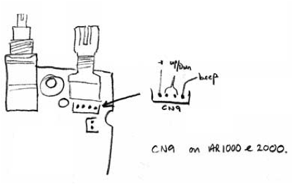
The keypad "BEEP" was present on early units but has been disabled later on. However by addition of a single wire, the facility can be restored.Switch the receiver off and remove the batteries. Disconnect the receiver from the AC charger and remove the rear case. 4 screws secure the rear case half (2 x in rear case - 2 x in battery box). You will see 3 PCB layers once inside the case.
One end of the wire connects to the outer edge of CN9 on the top PCB. This is located at the base of the rotary tuning control. The original wire is usually GREY and the "tail" can sometimes be seen. If this is the case, solder a new length of wire to the tail. If no tail is visible, solder a new length of wire to the corresponding point on the PCB. Use the foil side (facing upward) of the PCB, this will save you "taking the set to bits"!
The other end of the wire connects to the bottom PCB (which carries the microprocessor). Follow the 3 existing wires from CN9 to the bottom board. With the base of the set facing you an unused "LAND" will be visible on the PCB to the left of the 3 existing wires. If you are lucky a tail will be connected.
If you are very careful and use a small soldering iron then there is no need to separate the PCB's. Solder the free end of the new wire to the "LAND or Tail".
Re-assemble the case and test. You will now have a KEYPAD BEEP.
Note: If you find it necessary to separate the PCB's, then the earth bonding wires will need de-soldering from the edge of each PCB. Make sure you reconnect them when you re-assemble the receiver.
TOP
AR2000 Discriminator (detector) output
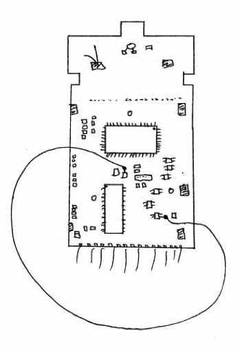
Remove the rear cover (4 screws) taking care not to damage the battery wires while pulling the case apart. The battery wires will unplug from the power supply board if required.The rear of the main PCB is now visible.
The discriminator output can be taken from IC5 pin9.
IC5 is located on the visible side of the board but is situated about 1/2 way down the board but on the edge (same side as the power socket).
It is labelled TA7761P although this may be difficult to read due to lacquer on the device.
Simply solder a wire to pin 9 of this IC to obtain the discriminator output.
Terminate the wire at a suitable socket and re-fit the case half (you may find that removing the side-panel case stopper provides an excellent location without the need to drill or burn a hole in the cabinet).
TOP
Please note that the information is supplied “as is” without any support nor obligation. This model is no-longer accepted for repair and none of the parts are available anymore.
www.aorja.com