AR2700 BULLETIN PAGE
This information is supplied as a convenience to our loyal customers still using discontinued legacy AOR receivers.
Please note that the information is supplied “as is” without any support nor obligation. This model is no-longer accepted for repair and none of the parts are available anymore.
| Reset |
| Opto-Scout Modification |
| Discriminator output |
| RU2700 record option fitting(pdf) |
| Keypad replacement |
AR2700 RESET
The AR2700 originally appeared with IF of 724.20 and 287.550MHz. In some areas of Europe, this led to compromised immunity from which required the change of about three or four components plus reprogramming of the CPU.To reprogram the original defaults:
Press & hold the [0] key and power the set on... switch it off again.
Press and hold the [5] key and power the set on.
"b00" is displayed. Check that the frequency displayed is "70.00000", if not key it in and press [ENT]. If "70.00000" is displayed just press [ENT].
The display will change to "b00 / 1IF" and a frequency. Check that 749.25000 is displayed, if not key it in and press [ENT]. If 749.25000 is displayed just press [ENT].
"b01" is displayed. Check that the frequency displayed is "108".00000, if not key it in and press [ENT]. If "108.00000" is displayed just press [ENT].
The display will change to "b01 / 1IF" and a frequency. Check that 749.25000 is displayed, if not key it in and press [ENT]. If 749.2500 is displayed just press [ENT].
"b02" is displayed. Check that the frequency displayed is "165".00000, if not key it in and press [ENT]. If "165.00000" is displayed just press [ENT].
The display will change to "b02 / 1IF" and a frequency. Check that 749.25000 is displayed, if not key it in and press [ENT]. If 749.2500 is displayed just press [ENT].
"b03" is displayed. Check that the frequency displayed is "470".00000, if not key it in and press [ENT]. If "470.00000" is displayed just press [ENT].
The display will change to "b03 / 1IF" and a frequency. Check that 749.25000 is displayed, if not key it in and press [ENT]. If 749.2500 is displayed just press [ENT].
"b04" is displayed. Check that the frequency displayed is "1013".00000, if not key it in and press [ENT]. If "1013.00000" is displayed just press [ENT].
The display will change to "b04 / 1IF" and a frequency. Check that 287.5500 is displayed, if not key it in and press [ENT]. If 287.5500 is displayed just press [ENT].
"b05" is displayed. Check that the frequency displayed is "1300".00000, if not key it in and press [ENT]. If "1300.00000" is displayed just press [ENT].
The display will change to "b05 / 1IF" and a frequency. Check that -287.5500 is displayed, if not key it in (ignore the minus sign) and press [ENT]. If 287.5500 is displayed just press [ENT].
"b06" is displayed. Check no frequency is displayed and a row of lines is displayed "- - - -". Press [0] [ENT].
The CPU will soft reset, all LCD legends will be displayed and the receiver will go to the previously used frequency.
| Notes: | If you are SLOW in programming it will return to "b00". You can abort entry by switching the receiver Off using the [PWR] key. A marginal improvement in sensitivity around 165MHz may be achieved by changing the frequency of "b02" from 165.00000 to 170.00000MHz. If you use the wrong setting no damage will occur, it simply will not receive! |
To reprogram the later production defaults:
Press & hold the [0] key and power the set on... switch it off again.
Press and hold the [5] key and power the set on.
"b00" is displayed. Check that the frequency displayed is "70.00000", if not key it in and press [ENT]. If "70.00000" is displayed just press [ENT].
The display will change to "b00 / 1IF" and a frequency. Check that 748.57500 is displayed, if not key it in and press [ENT]. If 748.57500 is displayed just press [ENT].
"b01" is displayed. Check that the frequency displayed is 108.00000, if not key it in and press [ENT]. If "108.00000" is displayed just press [ENT].
The display will change to "b01 / 1IF" and a frequency. Check that 748.57500 is displayed, if not key it in and press [ENT]. If 748.57500 is displayed just press [ENT].
"b02" is displayed. Check that the frequency displayed is "165".00000, if not key it in and press [ENT]. If "165.00000" is displayed just press [ENT].
The display will change to "b02 / 1IF" and a frequency. Check that 748.57500 is displayed, if not key it in and press [ENT]. If 748.57500 is displayed just press [ENT].
"b03" is displayed. Check that the frequency displayed is "470".00000, if not key it in and press [ENT]. If "470.00000" is displayed just press [ENT].
The display will change to "b03 / 1IF" and a frequency. Check that 748.57500 is displayed, if not key it in and press [ENT]. If 748.57500 is displayed just press [ENT].
"b04" is displayed. Check that the frequency displayed is "1013".00000, if not key it in and press [ENT]. If "1013.00000" is displayed just press [ENT].
The display will change to "b04 / 1IF" and a frequency. Check that 288.2250 is displayed, if not key it in and press [ENT]. If 288.2250 is displayed just press [ENT].
"b05" is displayed. Check that the frequency displayed is "1300".00000, if not key it in and press [ENT]. If "1300.00000" is displayed just press [ENT].
The display will change to "b05 / 1IF" and a frequency. Check that -288.2250 is displayed, if not key it in (ignore the minus sign) and press [ENT]. If 288.2250 is displayed just press [ENT].
"b06" is displayed. Check no frequency is displayed and a row of lines is displayed "- - - -". Press [0] [ENT].
* Programming can be aborted by switching the unit off with the power key.
The CPU will soft reset, all LCD legends will be displayed and the receiver will go to the previously used frequency.
I.F. data
| Receive frequency (MHz) | 1st IF (MHz) | 2nd Oscillator |
| 0.1 - 70 | +748.575 | 691.2 |
| 70 - 108 | +748.575 | 691.2 |
| 108 - 165 | +748.575 | 691.2 |
| 165 - 470 | +748.575 | 691.2 |
| 470 - 1013 | +288.225 | 345.8 |
| 1013 - 1300 | -288.225 | 234.8 |
2nd I.F. 57.375
AM/NFM 3rd IF 455kHz, 3rd local oscillator 56.920MHz
WFM 3rd IF 10.7MHz 3rd local oscillator 46.675MHz
TOP
AR2700 Opto Scout Modification
The hardware modification includes adding a small jack to the radio to make it possible to connect the Scout™ with a flexible cable using 2.5mm phone jacks cables, and plugs. The modification described will permit easy connection from the Scout™ to the radio for reaction tune operation. These modifications may however void the manufacturer's warranty. Keep this in mind and make sure you are aware of the possibility. Opto Electronics will not make these modifications to a customer's radio and will not assume any responsibility or liability for their effect on warranty service. Opto Electronics will not service or repair any AOR products.Having been warned, it can be stated that the addition of the jack described here as easily done by a qualified electronics technician who is experience in working on two-way radios and scanners. Careful soldering of the wires to locations shown is necessary. If you are not experienced at soldering or taking apart hand-held radios you should seek assistance from a qualified technician.
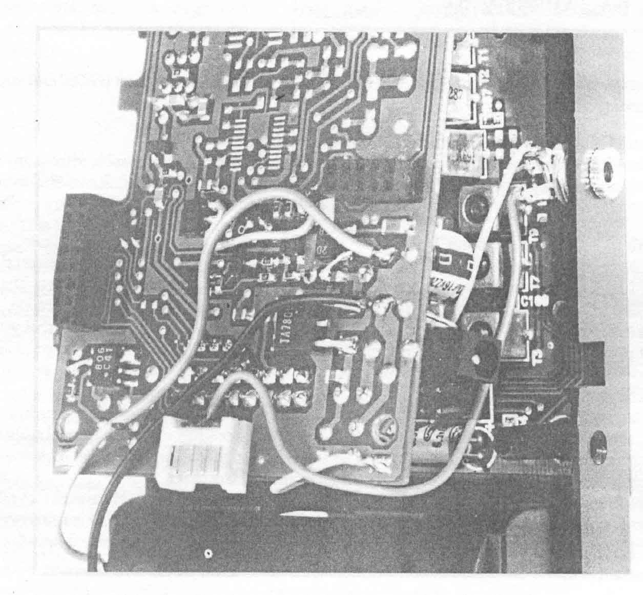
Disassemble the radio and check the jack location against the picture. Make sure all the batteries are removed and that the power adapter is disconnected. When modifying the AR2700 it is necessary to partially remove the center PC board as shown in picture (Do Not attempt to completely remove it from the unit!)
The jack being installed is a 2.5mm (3/32") phone jack. The center or tip connection from the Scout™ carries data to the radio. The wires used are number 24 stranded. In the AR8000, the wire lengths are short, a little more than an inch. In the AR2700, use wires 4" long and custom cut to length when installing.
It is not necessary to drill a hole for the jack. Locate the position of the hole relative to the power jack as shown in the picture. Tale a few minutes to see that the jack location will not interfere with the PC boards when the radio is re-assembled. To create a hole in the plastic case, use an X-Acto knife and place the point in the center of the desired location. Rotate the blade creating a hole in the soft plastic. Keep checking the hole size against the jack to make sure that you don't make it too large. It may be necessary to bevel the edge of the hole for the nut to fit on the jack. It is better to create the hole in this manner than to use a drill.
The ground connections can be made where ever it is convenient. The picture shown positions that work well. The data connection in the AR8000 is taken directly from a chip resistor (as shown). Solder carefully to prevent damage to the resistor. The AR2700 connection is a little more difficult to see. The wire is soldered directly to the second pin from the left on the white connector. Make sure the wire cannot move and short any other pin. Check for continuity between the nut on the outside of the jack and the ground connection to the radio's PC Board using a tester. If this checks out and polarity is not reversed then re-assemble the radio.
TOP
AR2700 Discriminator Output
The discriminator output on the AR2700 is taken from pin 9 of IC 200.This is a MC3372 device, and is the only device with this number in the set. This should make it easy to find !
The only other thing you require is an earth but this can be picked up at a convenient place elsewhere in the set.
TOP
AR2700 Keypad replacement
The AR2700 keypad is quite easy to replace requiring only some small screwdrivers. No soldering is required. The trickiest part is probably splitting and re-joining the two case halves.Remove 6 case screws. Two from inside the battery compartment and four down the sides of the set through the bottom case half (leave those through the top case half in place – the threaded backing pieces will otherwise become loose).
Pull the top and bottom case halves apart. These should be pulled straight apart rather than levered up from the top or bottom of the set. Two internal board connectors hold front and back together which will just pull apart (these are located on either side of the set close to the reset button and the power socket so you know where to pull). In addition to this, the speaker wire also goes from the front case to the rear section of the set, so don't let the case halves fly apart more than about half an inch. Once the case halves are split, this will have to be unplugged.
Don't worry about the control buttons down the side of the set at this point.
Working on the front panel.
Remove the two screws in the center of the board (just below the microprocessor).
Loosen the two screws at the top of the set.
Lift the board up from the bottom of the set and then lift it clear.
Any side buttons not already fallen out will almost certainly do so now.
Remove the keypad.
It's probably a good opportunity to clean out any dust from the display and glass with a fine brush or air-duster. If the board contacts aren't bright and shiny, give them a wipe over with a solvent cleaner (IPA or similar). Take care with the display window, it is only held in place with plastic lugs.
Fit the new keypad (it can only go one way).
Re-fit the front board. The keylock button has to fitted onto the switch before the board can be seated down. The switch has to be fitted so that the narrow part of the button is towards the front of the set. If you can't see which is the narrowest end, just try the button in the front case – the curve on the button should match the curve on the case. Putting it in upside down makes one end of the button stand proud.
Fit and tighten the center screws first before tightening those at the top of the set.
Slide in the '2nd F' and 'MONI' buttons. The same applies to the shape of these buttons as to the keylock button (i.e. the curve of the button should match the curve of the case).
Place the two case halves back together in such a way that the buttons don't fall out.
Re-fit the speaker connector.
Push the two case halves straight together taking care not to trap the speaker wire or battery wire. Ensure that the internal connectors go back together correctly.
The two case halves should push together with only a small amount of resistance. If they won't go easily together, don't force them – you have got something wrong or something trapped.
Refit the case screws and test your work.
TOP
www.aorja.com